- ARDUINO CNC SHIELD CLONE X AXIS HOW TO
- ARDUINO CNC SHIELD CLONE X AXIS MANUALS
- ARDUINO CNC SHIELD CLONE X AXIS INSTALL
Testing each stepper controller socket individually is critical.Ī.
ARDUINO CNC SHIELD CLONE X AXIS MANUALS
Pololu stepper drivers need adjustment and it’s good to have a read through their online manuals at 5. Open up a serial connection to the Arduino board and check if GRBL is running.(I use Putty to connect to GRBL) 4. Plug the shield into an Arduino board with a pre-installed copy of the GRBL Firmware. Do a visual check of all soldered points on the new board. The 36V are for drivers like the Pololu DRV8825 that can run on +36V.įirst Run To make sure all parts function as they should, we need to go through a pre-flight checklist. A4988 drivers are not designed to run at 36V and will blow up the first time you power them up at that voltage. That does not mean that all Pololu Stepper drivers can run that high. WARNING The Arduino CNC Shield supports power supplies up to 36V.
ARDUINO CNC SHIELD CLONE X AXIS INSTALL
Last but not least is to install the screw terminals for the power. I use the same principle as with the Arduino Board to align the Stepper Driver headers.ħ. Last bits are to Solder the Stepper driver headers in place. This ensures that the headers are always aligned and straight.Ħ. I usually do it by inserting the headers into an Arduino board and then by placing the shield on top of them before I soldering them in place. Before soldering the stepper driver headers in place it might be easier to solder the Arduino headers in place. Capacitors are usually marked with a ” – ” indicating the ground/negative lead.ĥ.

Then solder them in place making sure that positive lead is on the side with the ” + “. To mount the capacitors horizontally start by bending the capacitor leads 90 degrees.ī.

This also leaves a bigger gap between the capacitors and the stepper drivers allowing more ventilation. Because of the height of the capacitors needed, we decided to mount them horizontally utilizing all the space under the stepper drives. Week Robots Rostock Scara Shield Sketchup Stepper Driver Stepper MotorsĤ. Openbeam Openhardware PCB Pick and place Pinout Pololu Power Supply Python Grbl Hexapod Kicad Kickstarter Kossel Pro Laser cutter Lego Linux Milling Machine Byĭoing this the board will lean-to one side forcing the next pins you are working on to be inserted all the way into the board (Ready to be soldered in place). For me the easiest way is to start with pins on one side and work to the other side. Majority of the assembly work is soldering the provided header pins in place. Subscribe to Blog via Email Enter your email address to subscribe to this blog and receive notifications of new posts by email. Raspberry Pi CNC Board / HatĬonfiguring Grbl (Arduino Based CNC-Controller)Īrduino Float to String (That actually works)
ARDUINO CNC SHIELD CLONE X AXIS HOW TO
GRBL’s PWM functionality – How to control a laser or variable speed spindle. Written for Arduino's (G-code interprete r GRBL) Grbl (Arduino G-Code Processor) Pin Layout 2. Quick GRBL setup guide for Windows (Arduino G-Code Interpreter) GRBL Arduino Library - Use the Arduino IDE to flash GRBL directly to your Arduino Opensour (Version 3.03 and on does not need the Power Wire anymore.)

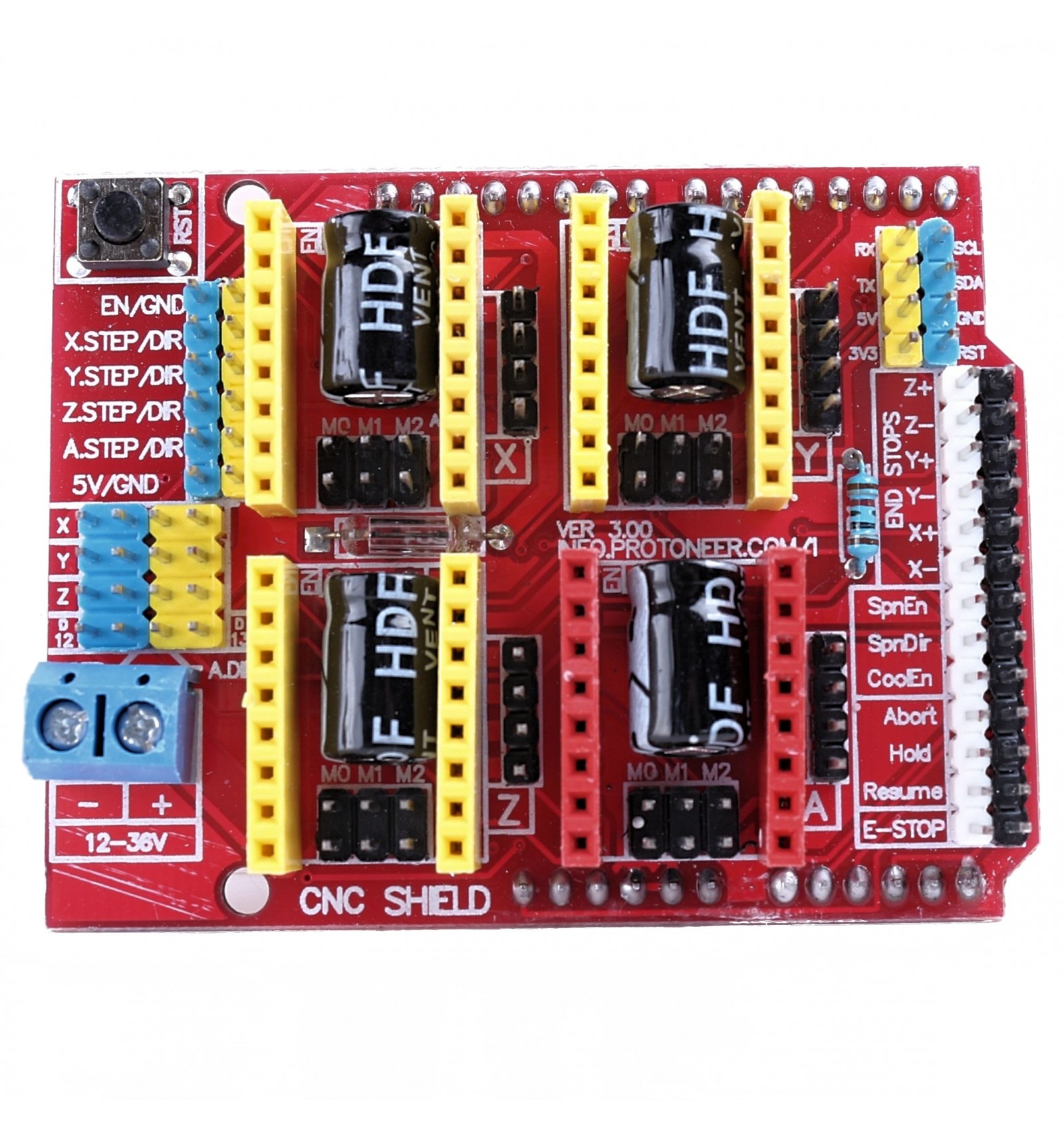
First step is to solder the Power Wire( or Fuse) and 10K (R1) resistor in place.

We also have a discussion forum for this board : /viewforum.php?f=6 Contents: Assem bly Steps First Run Jum per Settings.Īrduino CNC Shield V3.XX – 1. This is a quick guide to help with assembling the Arduino CNC Shield V3.XX. Arduino CNC Shield V3.XX – Assembly Guide | .nzĪrduino CNC Shield V3.XX – Assembly Guide 9 5:25 pm / Bertus Kruger


 0 kommentar(er)
